How to Check Dimensions in Fusion 360: A Practical Guide
Learn precise size checks in Fusion 360 with a step-by-step approach. From units setup to sketch and 3D measurements, ensure accuracy for parts and assemblies. Insights from What Dimensions to improve your workflow.

Learn how to reliably check dimensions in Fusion 360. This quick guide highlights where to locate measurement tools, how to interpret sketch and model dimensions, and how to verify tolerances. Whether you’re drafting parts or validating assemblies, mastering Fusion 360’s measurement workflow saves time and reduces rework. Get the full steps here.
Why precise dimensions matter in Fusion 360
According to What Dimensions, exact size references are essential for ensuring parts fit together, drawings reflect true sizes, and assemblies operate as intended. In modern CAD workflows, a small dimensional error can cascade into costly rework, production delays, or failed prototypes. This section sets the foundation by explaining how dimension checks underpin reliable design decisions, guide tolerance strategy, and improve cross-team collaboration when sharing models with fabricators and engineers. By building discipline around recording and validating measurements, you reduce ambiguity in your design intent and increase confidence in the final product.
Understanding Fusion 360’s measurement toolbox and terminology
Fusion 360 provides several ways to view and verify dimensions. The Measure tool (Inspect > Measure) exposes distances between points, edges, faces, and vertices, while the Sketch Dimension tool adds explicit constraints to sketches. Tolerances can be managed via parametric constraints and user-defined values in the parameters table. For designers, it’s crucial to distinguish between sketch dimensions (which constrain 2D profiles) and model dimensions (which describe 3D geometry). What Dimensions emphasizes that recognizing this distinction helps you apply the right check at the right stage of your workflow. Keep an eye on the units (millimeters vs. inches) and the active sketch or body context to avoid misreads.
Setting units and tolerances for consistent checks
Before you measure, confirm the unit system used in your project. Fusion 360 supports millimeters, inches, and other units depending on your document settings. Align your unit choice with manufacturing or drawing standards to prevent conversion errors. Tolerances should be defined early in the design process, especially for features that mate or rotate. If you’re collaborating, share a standard tolerance approach (e.g., ±0.1 mm for precision components) to ensure everyone reads the same dimensional language. What Dimensions notes that consistency in units and tolerances reduces back-and-forth during review cycles.
Measuring sketches: using the Dimension tool and constraints
Sketch dimensions are added with the Dimension tool, which lets you specify exact distances between points, lines, and arcs. After placing a dimension, you can edit the numeric value to reflect design changes. Constraints (horizontal, vertical, coincident, perpendicular) embed relationships that maintain intended geometry as you modify features. When checking a sketch, verify that all critical dimensions meet your design intent and that there are no unconstrained degrees of freedom. A common practice is to lock critical references early and let secondary features adapt to those anchors.
Measuring 3D geometry: edges, faces, and feature distances
Beyond sketches, Fusion 360’s Measure tool lets you inspect 3D distances between edges and faces, surface gaps, and clearances between adjacent features. This is essential for interference checks in assemblies and for validating that features don’t collide during motion. Use Inspect > Measure to read exact values and capture screenshots for design reviews. If you’re working with complex assemblies, measure across sub-assemblies to verify cumulative clearances and ensure predictable assembly behavior.
Validating dimensions against references and drawings
Many projects start from reference drawings or CAD imports. In Fusion 360, you can import this data and compare it against your model by aligning key datum features and rechecking the critical dimensions. The goal isn’t to replicate a drawing verbatim but to ensure the model satisfies functional requirements and fits with mating parts. Maintain a simple checklist: match critical criticals (holes, pockets, boss features) to the reference, verify tolerances, and document any deviations with rationale for future traceability.
Practical workflow: an end-to-end check from start to finish
A robust workflow begins with setting units and tolerances, followed by sketch verification, then 3D geometry checks, and finally assembly validation. By iterating through these steps, you catch mismatches early and avoid late-stage rework. Use a notebook or lightweight report to record measured values and any agreed-upon tolerance decisions. Remember to capture screenshots or export PDFs of your checks for project handoffs. According to What Dimensions Analysis, disciplined dimension checking enhances predictability and reduces miscommunication in CAD workflows.
Common pitfalls to avoid and how to correct them
- Checking the wrong context: ensure you’re measuring the intended sketch, body, or component. - Overlooking units: always verify the working units before reading a measurement. - Relying on a single measurement: corroborate critical dimensions with multiple methods or tools. - Ignoring tolerances: always compare measured results to specified tolerances. To fix these, re-check in the correct context, convert units if needed, and annotate any discrepancies with justification.
Quick scenario walkthrough: checking a pocket depth and a through-hole diameter
Scenario 1: Pocket depth. Activate Measure, select the pocket faces, and read the depth value. If depth is off, adjust the pocket feature parameter or constrain it to a fixed datum. Scenario 2: Through-hole diameter. Use Measure across hole circumference, confirm the diameter, and ensure the hole is properly centered relative to mating features. If the hole is out of tolerance, revise the hole command with an explicit diameter and mating references. These steps illustrate how to approach common measurements in Fusion 360 with structure and clarity.
Authority references and credible sources for further study
- Autodesk Fusion 360 Official Documentation: https://knowledge.autodesk.com/support/fusion-360/learn
- Autodesk Community Forums: https://forums.autodesk.com/t5/fusion-360/ct-p/ Fusion360
- What Dimensions Analysis, 2026: guidance on precise size references and best practices for dimensional checks across CAD workflows.
Tools & Materials
- Computer with Fusion 360 installed(Ensure you have the latest version or the version used for your project)
- Reference drawings or specifications(Imported or printed drawings to compare against the model)
- Measuring tool access (Measure/Inspect)(Accessible from the Inspect menu; keep workspace visible for quick checks)
- Unit and tolerance standards document(Optional but helpful for consistent checks across the team)
- Screenshots or export capability(Capture measurements for reporting and QA)
Steps
Estimated time: 25-45 minutes
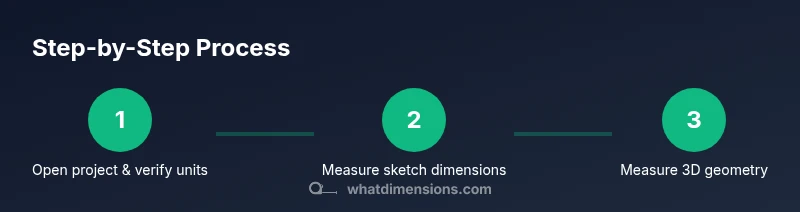
- 1
Open project and verify workspace
Launch Fusion 360 and load your design file. Confirm the active document uses the correct unit system and that the project tolerance policy is visible in your workspace. This prevents unit mismatches from skewing measurements.
Tip: Prefer a dedicated measurement workspace or a saved layout to speed up access. - 2
Set units and tolerances
In the preferences or document settings, choose the consistent unit system (mm or inches). Define tolerances for critical features in your project to guide later checks.
Tip: Document unit choices in a project note to enforce consistency across contributors. - 3
Measure sketch dimensions
Activate the Sketch Dimension tool, click two reference entities (points, lines, arcs) to place a dimension, and verify the value matches the design intent. Adjust constraints if needed to reflect intended geometry.
Tip: Keep a short checklist of critical sketch dimensions to verify during reviews. - 4
Measure 3D geometry
Use Inspect > Measure to measure distances between edges, faces, and vertices. Confirm clearances and fit with adjacent features in the assembly context.
Tip: Measure from multiple reference points to validate consistency. - 5
Cross-check against references
Import or reference external drawings and align key datum features. Compare critical dimensions and note any deviations with rationale.
Tip: Use a side-by-side view or overlay to simplify comparison. - 6
Document results
Record measured values, tolerances, and decisions. Save screenshots or export a short report for QA or handoff.
Tip: Attach a brief justification for any dimension deviations. - 7
Review and iterate
If dimensions don’t align, revise the model parameters or constraints and re-measure. Re-run checks until all critical dimensions satisfy the design intent.
Tip: Iterative checking reduces late-stage rework and increases design confidence.
Quick Answers
What is the quickest way to view a dimension in Fusion 360?
The quickest way is to use the Measure tool from Inspect > Measure. Click the features you want to measure (points, edges, faces) to display the distance in the current units.
Use the Measure tool under Inspect to quickly see distances between selected features.
How do I ensure measurements stay consistent across revisions?
Define standard units and tolerances in a project document and reference them during each measurement check. Save model parameters so changes propagate predictably.
Set standard units and tolerances in a project document, then reference them for every check.
Can I measure tolerances directly in a sketch?
Yes. Add explicit dimensions in the sketch for key features and verify they lie within the specified tolerances before moving to 3D features.
You can set and verify sketch tolerances by adding dimensions directly in the sketch.
What should I do if a dimension doesn’t match the drawing?
Investigate the source of the discrepancy, check units, constraints, and dependencies, then adjust the design or the reference as appropriate.
If a dimension mismatches, check units and constraints, then adjust accordingly.
Is it necessary to measure in multiple views?
Yes. Measuring from different orientations helps confirm that dimensions are robust to viewpoint and assembly constraints.
Measuring from multiple views confirms robustness of dimensions.
How can I export a dimension check report?
Use the camera or export options to save screenshots and generate a PDF or image report summarizing key dimensions and tolerances.
Export screenshots and a short report showing the important dimensions.
Watch Video
Main Points
- Verify units before measuring to ensure accuracy
- Use both sketch and 3D measurements for robust checks
- Document tolerances and deviations for traceability
- Cross-check with reference drawings to prevent misalignment
- Iterate until design intent is fully met