Dimensions of Steel Beams: A Practical Sizing Guide
Understanding steel beam dimensions—nominal depth, flange width, and web thickness—and how they influence strength, weight, and fit. A data-driven, standards-focused guide to reading, selecting, and applying I-beams and wide-flange shapes.

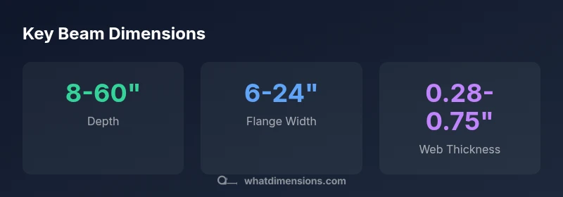
Steel beam dimensions vary by shape and standard, with common W-shape depths ranging from about 8 to 60 inches, flange widths from roughly 6 to 24 inches, and web thickness typically between 0.28 and 0.75 inches. Dimensions are designated as nominal depth, flange width, and web thickness and are governed by regional standards such as AISC and EN guidelines, depending on project requirements.
What dimensions mean for steel beams
According to What Dimensions, dimensions on a steel beam are more than numbers on a drawing; they define what the beam will weigh, how it will perform, and how it will fit within a structure. The three primary dimensions engineers use are nominal depth (the overall height of the beam), flange width (the width of the flat top and bottom plates), and web thickness (the vertical member that connects the flanges). In practice, these measurements are specified in inches (or millimeters in metric contexts) and are derived from standardized shapes such as I-beams and wide-flange W-shapes. While modern manufacturers publish dozens of sizes, most projects center on a few families that cover a broad range of loads and spans. The distinction between nominal and actual dimensions matters: the nominal size roughly conveys capacity, while the actual finished size can vary by tolerance and treatment. Typical practical ranges for general construction place depth from about 8 inches up to 60 inches, flange widths from roughly 6 to 24 inches, and web thickness from about 0.28 to 0.75 inches. These ranges reflect broad application—from light residential framing to heavy industrial frames—and illustrate why designers often start with standard shapes before moving to custom sizes.
Shape families and their dimensions
Beams come in several families, but two dominate structural design: I-beams and wide-flange (W) shapes. I-beams have thinner flanges relative to depth, which makes them efficient for certain spans, while W-shapes offer a broader profile that increases bending resistance for tall, load-bearing frames. Dimensions of these shapes are defined by depth, flange width, and web thickness, but the distribution varies: I-beams often appear with more slender flanges and heavier webs in the same depth class, whereas W-shapes emphasize larger flanges for higher section moduli. Across both families, a wider flange generally improves bending strength and reduces local buckling, but at the cost of weight and ease of fabrication. In practice, engineers select shapes from standard catalogs that group sizes by depth bands (for example, shallow, mid-range, and deep sections) to streamline procurement and ensure compatibility with connections, bolts, and welds. As a designer, you’ll compare the depth-to-flange ratio (a proxy for stiffness) and the available moment of inertia to ensure the beam meets both strength and deflection criteria for the job.
Reading the drawings: nominal vs actual and units
On drawings, the dimension you see is often the nominal size, such as W12x26 or I-beam 8x18, which is a shorthand indication of a family and depth class. The actual cross-section, measured in the produced beam, may differ slightly due to machining, camber (a slight curvature introduced during rolling), and tolerances specified by codes. It is essential to note units: in the United States, inches are standard and should be consistent across the project; in many other regions, millimeters are used. Tolerances matter because even small deviations can affect fit at connections and the overall stiffness of the member. When reviewing drawings, cross-check the “as-rolled” or “as-fabricated” dimensions against the stated tolerances, and confirm whether the beam will be cut to length and whether any chamfers or preparation (holes for bolts) are included. Keep in mind that the nominal depth and flange width define the primary capacity, while the web thickness contributes to shear capacity and buckling resistance.
How dimensions influence structural performance
Depth is the primary driver of bending resistance: deeper beams have higher section modulus and greater resistance to bending moments, improving stiffness and reducing deflection under load. Flange width contributes to overall stiffness and shear capacity; wider flanges spread stress and help prevent web buckling under high loads. Web thickness affects local buckling and shear capacity; thicker webs resist lateral-torsional buckling in certain configurations. The interaction of these three dimensions—depth, flange width, and web thickness—determines the beam’s capacity, weight, and cost. In practice, designers look for a balance between depth (for strength and spacing), flange width (for connection compatibility and stiffness), and web thickness (for web shear and buckling resistance). When dimensions are matched with appropriate steel grades and connections, structures perform reliably under gravity loads, wind, and seismic events across many construction contexts.
Practical size ranges by application
For light residential framing, beams often occupy the shallower end of the spectrum, with depths in the single-digit to low-double-digit inches range and modest flange widths. In mid-rise commercial and office buildings, mid-range depths and wider flanges are common to support floors and skylights with moderate spans. Industrial facilities and heavy warehouse structures may require deeper sections and thicker webs to tolerate higher loads and longer spans. The exact dimensions depend on local codes, live and dead loads, span length, support conditions, and connection details. To illustrate, broad ranges you’ll encounter include nominal depths from roughly 8 to 60 inches, flange widths from about 6 to 24 inches, and web thicknesses around 0.28 to 0.75 inches. When budgets constrain size, engineers may substitute a deeper beam with a wider flange or adjust spacing to achieve the same stiffness. Always verify with project specifications and a structural engineer to select the appropriate size for safety and economy.
How to select beam dimensions for a project
Follow a disciplined sizing workflow:
- Step 1: Establish design loads from structural analysis, floor plans, and environmental considerations.
- Step 2: Determine the required span and desired deflection limits, noting serviceability criteria.
- Step 3: Choose a beam family (I-beam or wide flange) and identify a candidate depth-band that meets strength requirements without excessive weight.
- Step 4: Compare section properties (depth, flange width, web thickness) to achieve the target moment of inertia and section modulus; consider connection details, bolt patterns, and welding.
- Step 5: Check tolerances, fabrication allowances, and practical installation constraints such as clearance and access for hoisting.
- Step 6: Validate the selection against codes (AISC/EN) and project specifications, then coordinate with fabricators to confirm available stock sizes. This process emphasizes starting from standard catalog sizes, then refining via structural analysis and practical constraints, ensuring a cost-effective yet safe solution.
Manufacturing tolerances and installation considerations
Manufacturers produce steel beams within defined tolerances that influence how precisely members fit at joints. Tolerances affect alignment, bolt placement, and weld geometry, so it’s critical to confirm the exact finished sizes before fabrication. Typical issues include camber correction after installation, misalignment at supports, and slight deviations in length due to cutting and end-prep. Contractors often use shims, adjustable connections, and field measurements to accommodate real-world conditions. Remember that coatings, painting, and corrosion protection add to the overall dimensions; plan for these when calculating fit at connections and in tight spaces. In all cases, document the tolerances in the shop drawing package and verify match with field conditions to avoid costly rework.
Common beam dimension ranges
| Beam Type | Nominal Depth (in) | Flange Width (in) | Web Thickness (in) |
|---|---|---|---|
| W-shape (wide flange) | 8-60 | 6-24 | 0.28-0.75 |
| I-beam (standard) | 6-40 | 4-12 | 0.28-0.60 |
Quick Answers
What does the term nominal depth refer to in steel beams?
Nominal depth is the height designation used for sizing and specification. The actual depth can vary slightly due to manufacturing tolerances and finishing processes; always confirm exact measurements on the shop drawing.
Nominal depth is the size name used in catalogs; actual depth may differ by a bit when the beam is made.
Which units are used for beam dimensions in typical projects?
In the US, dimensions are usually in inches; elsewhere, millimeters are common. Always ensure unit consistency across drawings, fabrication, and installation to avoid misfits.
Most often inches in the US; millimeters in many other regions—keep units consistent.
What is the difference between nominal and actual dimensions?
Nominal dimensions indicate size class and are used for specification. Actual dimensions reflect finished product after tolerances are applied. The two can differ slightly, impacting fit at joints.
Nominal is the size label; actual is what you get after manufacturing.
How do dimensions affect beam load capacity?
Depth, flange width, and web thickness together determine bending strength and stiffness. Deeper beams and wider flanges generally increase capacity, but also weight and cost.
More depth and bigger flanges usually mean stronger beams, but you’ll pay more in weight and price.
Can I substitute a different beam size for a given span without reanalysis?
Substituting beam sizes requires re-analysis of the structural system, including connections and deflection. Do not change sizes without engineering review and code justification.
Don’t swap sizes without rechecking the design with an engineer.
What is camber and how does it affect on-site dimensions?
Camber is a slight upward curve rolled into many beams to compensate for sag under load. On-site measurements should account for camber to ensure joints align under service conditions.
Camber is a built-in curve; plan for it when installing beams.
“Beam dimensions are the backbone of structural sizing; selecting the right section reduces weight and cost while meeting performance targets.”
Main Points
- Know the three primary dimensions: depth, flange width, web thickness
- Read nominal vs actual sizes and verify tolerances
- Choose beam shapes based on depth, flange width, and web thickness balance
- Use standard catalogs first, then confirm availability with fabricators
- Ensure unit consistency (inches vs millimeters) across all drawings